Hotspots can quietly damage thin-film solar modules before a visible burn mark appears. Local heating may begin with partial shading, conductive debris, moisture ingress, cell-line defects, or poor electrical connections. Because thin-film technologies use different layer structures, their failure patterns cannot be judged like conventional crystalline-silicon panels.
Dr. Dirk Jordan, a photovoltaic reliability specialist at the National Renewable Energy Laboratory, has stated, “Reliability depends on understanding failure mechanisms, not simply recording failures.” This principle guides the question, “How to prevent hotspots on thin-film solar modules?” A credible answer begins with module-quality checks, careful handling, correct string design, and accurate installation records. Technicians should inspect shaded areas, connectors, junction boxes, and cable routes before commissioning. Thermal imaging can reveal abnormal temperature patterns. Electroluminescence testing may identify hidden defects, although results can vary across thin-film technologies.
Small details matter.
Keep leaves, dust, and bird residue from forming narrow shaded strips. Confirm that mounting clamps do not press against active areas. Check torque values instead of trusting appearance. During operation, compare thermal images with voltage and current data. One warm spot does not always prove a module failure. Wind, reflections, loose connections, or measurement errors can mislead the diagnosis.
No checklist is perfect. Field conditions change, and thin-film modules may react differently across climates and installation designs. A practical prevention plan therefore combines manufacturer guidance, trained inspection, routine cleaning, electrical testing, and documented follow-up. The strongest approach is not dramatic. It is consistent, evidence-based, and willing to question its own assumptions.
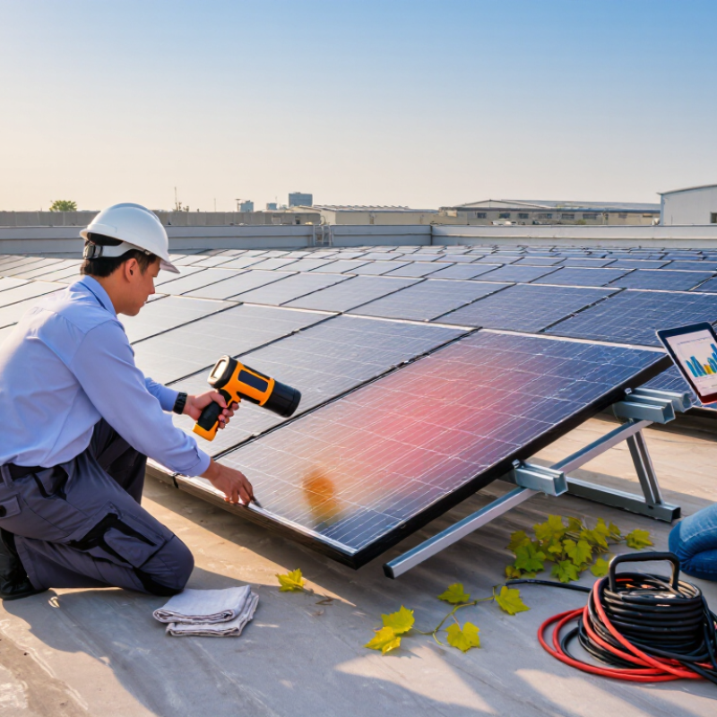
Hotspot prevention begins with a risk map, not a cleaning schedule. Under 1,000 W/m² STC, mark fixed obstructions, tree movement, parapet shadows, and row-to-row shading. Record the pattern at morning, noon, and late afternoon. Seasonal changes matter. A winter shadow can disappear in summer, then return unexpectedly. Use site drawings, calibrated irradiance sensors, and infrared inspections to compare electrical output with thermal behavior.
Soiling needs a finer map. Dust lines, bird deposits, and water stains rarely cover a module evenly. Uneven deposits create current mismatch and may stress shaded sections. After dry periods, inspect the lower edges and frame channels first. Compare soiling measurements with string current and module temperature. Cleaning intervals should follow local dust loading, not a generic calendar. That approach is practical, but imperfect.
Mismatch risks require electrical verification. Trace string I-V curves after commissioning and after major maintenance. Investigate unusual knees, reduced fill factor, or repeated low-current behavior. Confirm thin-film module bypass paths and operating limits through certified technical documents. Thermal images should be taken under stable sunlight, ideally near STC conditions, but real sites seldom stay perfectly stable. One inspection can mislead. Recheck suspicious areas under different irradiance levels. Small shading defects may look harmless today, yet become damaging when dirt, heat, and repeated cycling combine.
Thin-film projects need hot-spot prevention designed into the layout, not added during commissioning.
IEC 61215:2021, test 10.9, evaluates module resistance under defined hot-spot conditions and thermal stress. It is a qualification screen, not a field guarantee. Partial shading from rails, clamps, dust, or nearby vegetation can still create uneven current paths.
Use the IEC test as a design reference.
Map every likely shade line across the thin-film segments. Keep electrical segment lengths consistent, and avoid layouts that force one shaded section to carry current from larger unshaded areas. Place integrated bypass paths near vulnerable circuit groups where the module architecture allows it. Check row spacing during winter mornings, not only at noon. Small geometry errors matter.
The IEA PVPS Trends 2024 report recorded about 447 GW of new photovoltaic capacity in 2023, pushing global capacity beyond 1.6 TW.
More installations mean more unusual shading conditions in the field. Fraunhofer ISE’s Photovoltaics Report also documents continued reductions in module costs, encouraging denser system designs. Density saves land, but it can reduce shading tolerance. Thermal imaging during commissioning can reveal a warm segment before damage develops. A passing IEC result may hide weaknesses in real arrays.
Our own layouts should be challenged harder than the minimum test.
2026 Top Ways to Prevent Hotspots on Thin Film Modules
Hotspots begin with uneven current flow, partial shading, cracks, or weak bypass protection. Thin film modules still need careful thermal management. A 15°C thermal deviation across one module deserves investigation, not dismissal. Infrared inspections can reveal warm strips, isolated cells, and junction-box heating before visible damage appears. The IEA PVPS Task 13 reports that hotspot heating remains a recurring photovoltaic module failure mechanism. Heat accumulates quickly under poor airflow.
Control cell temperature through clear spacing, clean surfaces, and unrestricted rear ventilation. Measure module temperature during high irradiance, especially after rain or dust events. IR cameras should be calibrated and used with electrical data. A bright thermal image alone can mislead. NREL degradation research commonly uses about 0.5% annual power loss as a planning benchmark, but localized hotspots can accelerate losses far beyond normal aging. That comparison needs humility.
Tips: Scan modules near solar noon. Compare adjacent strings. Mark any area above the local average by 10–15°C. Check shading from cables, clamps, and nearby vegetation. Recheck after cleaning. Inspect connectors and bypass paths with qualified technicians. Keep records with images, irradiance, ambient temperature, and operating current. Do not rely on one inspection. Thermal patterns change with wind and load. A useful alert threshold may need site-specific adjustment, because a fixed number cannot represent every module, climate, or mounting design.
At 85°C and 85% relative humidity, thin-film modules face a demanding PID stress condition. Heat accelerates ion movement, while moisture reduces insulation resistance at vulnerable interfaces. This can drive leakage currents through the active layer, frame, or mounting system. Output loss may develop quietly before a visible hotspot appears. Small leaks matter. Actual risk depends on module construction, edge sealing, grounding, and installation quality. The 85/85 condition is useful, but it does not predict every outdoor result.
Choose modules with documented PID resistance under relevant humidity and temperature testing. Review the test method, exposure time, electrical bias, and measured power loss. A vague “PID resistant” claim is not enough. Inspect edge seals for cuts, wrinkles, and incomplete bonding during receiving and installation. Keep water paths away from junction areas, cable entries, and frame interfaces. Use compatible insulating materials, and verify grounding continuity before energization. Do not assume a dry warehouse proves long-term protection.
After commissioning, record insulation resistance, string current, and module temperature patterns. Repeat these checks after prolonged rain, heat waves, and unusual energy decline. Thermal imaging can locate warm cells, but it cannot identify PID alone. Pair it with IV tracing, visual inspection, and laboratory analysis when needed. In field work, maintenance teams sometimes chase shading first and overlook humidity-driven leakage. That mistake is understandable, yet it delays the real repair. Better designs reduce the opportunity for moisture, voltage, and heat to act together.
Hotspots in thin film modules rarely appear without warning. They often begin with shading, dirt, moisture, or poor connections. Annual electroluminescence (EL) and infrared (IR) inspections can reveal these changes before visible damage spreads. During an EL test, a qualified technician energizes the module and photographs weak cells, dark bands, and discontinuities. These images provide a useful baseline for later comparison. They also expose defects that normal daylight inspection may miss.
IR inspection adds operating evidence. Scan modules under stable sunlight and electrical load, preferably near midday. A small thermal island may indicate resistance, localized damage, or uneven current flow. Record irradiance, wind, ambient temperature, and module temperature with every scan. Context matters. A hot frame is not automatically a hotspot. Loose connectors, reflections, and temporary shading can create misleading readings. Comparing neighboring modules often gives the clearest signal.
Maintenance teams should map each finding by row, module, and image reference. Recheck abnormal areas after cleaning and shading removal. Persistent temperature differences deserve controlled electrical testing and qualified repair planning. Do not treat one annual visit as a guarantee. Weather, soiling, and image quality can hide problems. I have seen clean reports become less useful when technicians omitted operating conditions. That is an avoidable weakness. Keep evidence consistent, review trends yearly, and revise inspection intervals when repeated thermal or EL defects appear.
Map fixed obstructions, moving trees, parapet shadows, and row-to-row shading. Record conditions morning, noon, and late afternoon. Seasonal shadows matter. Cleaning alone cannot solve shading.
Shading creates uneven current paths across electrical segments. A small shaded area may heat when surrounding sections remain strongly illuminated. Dirt and repeated thermal cycling can worsen the stress.
Check dust lines, bird deposits, water stains, lower edges, and frame channels. Deposits rarely spread evenly. Compare soiling with string current and module temperature. Inspect again after dry weather.
Follow local dust loading rather than a fixed calendar. Measure actual buildup and compare electrical performance. This approach is practical, but imperfect.
Trace string current-voltage curves after commissioning and major maintenance. Look for unusual curve knees, reduced fill factor, or repeated low-current behavior. Recheck abnormal strings.
Infrared images can reveal warm segments before visible damage develops. Use stable sunlight when possible. One inspection can mislead. Recheck suspicious areas under different irradiance levels.
Use the test as a design reference, not a field guarantee. Map likely shade lines across thin-film segments. Keep segment lengths consistent. Avoid forcing shaded sections to carry larger unshaded areas.
Place suitable bypass paths near vulnerable circuit groups when the module design permits. Check row spacing during winter mornings. Small geometry errors matter. Dense layouts need extra scrutiny.
Preventing hotspots on thin-film solar modules requires a systematic approach to shading, soiling, and electrical mismatch. How to prevent hotspots on thin-film solar modules? Begin by mapping potential risk areas under 1,000 W/m² standard test conditions, then design module layouts that minimize uneven current flow and comply with IEC 61215 hot-spot testing principles. Proper spacing, balanced strings, and effective ventilation can help limit localized heating caused by partial shading or dirt accumulation.
Long-term protection also depends on thermal and environmental control. Monitor cell temperatures, infrared patterns, and thermal deviations exceeding approximately 15°C to identify developing faults early. Modules should also be evaluated for potential-induced degradation under high-temperature, high-humidity conditions, including exposure near 85°C and 85% relative humidity. Annual electroluminescence and infrared inspections can reveal hidden cracks, inactive areas, connection problems, and emerging hot spots before they reduce performance or create safety concerns.

Sypower Solar